【原理解析】HAMi × NVIDIA | GPU 拓扑感知调度实现详解
HAMi 社区在 v2.7.0 版本中正式推出了针对 NVIDIA GPU 的 拓扑感知调度 功能。此特性主要解决高性能计算(HPC)和 AI 大模型训练场景下的多卡通信瓶颈问题,通过智能调度,将计算任务精确部署到物理连接最紧密、通信速度最快的 GPU 组合上,从而最大化加速计算任务,提升集群整体的算力效能。
本文将在功能介绍的基础上,深入代码实现,详细剖析 HAMi 在支持 NVIDIA GPU 拓扑感知调度时的具体设计与实现原理。
一、核心特性总览
- 动态计算拓扑分数:Device Plugin 能够通过 NVML 动态探测节点上 GPU 间的物理连接拓扑(如 NVLink、PCIe),并将其量化为设备间的"通信分数",为调度提供决策依据。
- 双策略防碎片调度:
Fit函数内置了一套"深谋远虑"的寻优算法,针对"多卡任务"和"单卡任务"两种场景,会自动采用"最佳匹配"与"最小破坏"策略,保护集群拓扑资源的长期健康。
二、核心原理
HAMi 对 NVIDIA GPU 的拓扑感知调度,其核心设计思想是:首先在节点本地将复杂的物理拓扑精确地量化为设备间的"通信分数"。然后,调度器在决策时,基于这些分数做出最终的、最优的选择。
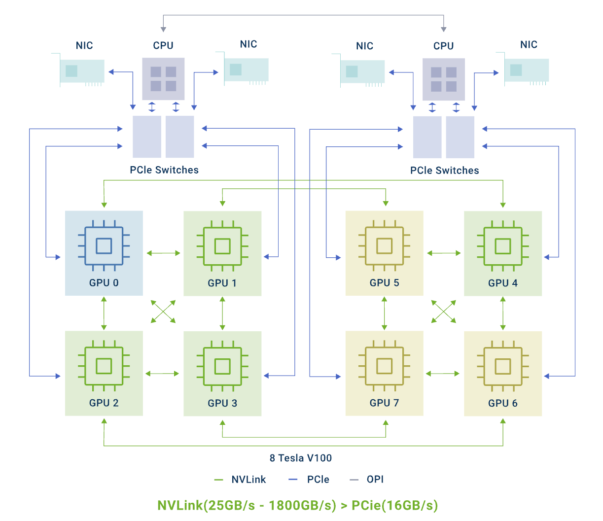
其核心分为 "拓扑注册" 和 "调度决策" 两个阶段:
阶段一:拓扑注册 - 将物理拓扑量化
此阶段的目标是将节点上不可见的 GPU 物理连接,转化为调度逻辑可以理解的、标准化的数字分数。
- 信息探测:在每个 GPU 节点上,Device Plugin 通过 NVIDIA 的 NVML 获取所有 GPU 两两之间的物理连接类型(NVLink 或 PCIe)。
- 数据建模与量化:探测结果并未构建成一个"连接矩阵",而是通过一个更精细的两步过程进行建模与量化:
- 构建拓扑图:首先,代码在内存中为节点构建一个完整的 GPU 拓扑图,其中包含了所有 GPU 之间的详细连接信息。
- 量化为分数:随后,算法遍历该拓扑图,根据预设规则(如
SingleNVLINKLink得 100 分,P2PLinkCrossCPU得 10 分),将任意两块 GPU 间的连接关系,计算并转换为一个具体的"通信分数"。
- 最终产物 - 设备分数表:最终产物是一个"设备分数表"。这个表记录了每个 GPU 的 UUID,以及它与其他所有 GPU 之间的通信分数,并被注册到节点的 Annotation 中。
阶段二:调度决策 - 智能选择最优解
调度器在收到任务后,会将"如何选择设备"这个问题,连同节点的"设备分数表",一同委托给设备端的 Fit 函数。
- 过滤:
Fit函数首先会过滤掉不满足基本资源需求(如显存、算力)的 GPU。 - 打分与寻优:随后,
Fit函数会基于"设备分数表",执行内置的、考虑了"最佳匹配"和"最小破坏"原则的寻优算法,在所有合格的 GPU 中计算出最优的组合,并将结果返回给调度器。
三、原理实现:代码深度解析
1. 拓扑发现与分数计算
拓扑信息的发现与量化,是所有后续智能决策的基础。整个过程在 Device Plugin 本地完成,并最终生成一个可供上报的分数表。
构建拓扑图 (build() function)
该逻辑主要由 pkg/device/nvidia/calculate_score.go 中的 build() 函数完成。它并非构建一个简单的连接矩阵,而是:
- 初始化设备列表:创建一个
DeviceList,其中每个Device对象都包含一个空的Linksmap (map[int][]P2PLink)。 - 遍历与填充:通过双重循环遍历所有 GPU 对 (
d1,d2),并调用GetP2PLink和GetNVLink(这两个函数在links.go中实现)。 - 聚合连接信息:将探测到的所有连接(包括 PCIe 和 NVLink)作为
P2PLink对象,追加到对应Device的Linksmap 中。这就在内存中构建了一个包含丰富连接信息的完整拓扑图。
量化为分数 (calculateGPUPairScore() function)
在拓扑图构建完成后,calculateGPUScore 函数会调用 calculateGPUPairScore 来将图中的连接关系转换为数字分数。
该函数会检查两个 GPU 之间的所有连接,并根据一个详细的 switch 语句进行评分。例如 P2PLinkSameBoard 得 60 分,而 SingleNVLINKLink 得 100 分,TwoNVLINKLinks 得 200 分。最终的分数是所有连接分数的总和。
// File: pkg/device/nvidia/calculate_score.go

func (o *deviceListBuilder) build() (DeviceList, error) {
        // ...
        // 1. 初始化一个扁平化的 DeviceList
        var devices DeviceList
        for i, d := range nvmlDevices {
                // ... create device object ...
                devices = append(devices, device)
        }

        // 2. 遍历并填充 Links map
        for i, d1 := range nvmlDevices {
                for j, d2 := range nvmlDevices {
                        if i != j {
                                // 获取并追加 P2P Link 信息
                                p2plink, _ := GetP2PLink(d1, d2)
                                devices[i].Links[j] = append(devices[i].Links[j], P2PLink{devices[j], p2plink})

                                // 获取并追加 NVLink 信息
                                nvlink, _ := GetNVLink(d1, d2)
                                devices[i].Links[j] = append(devices[i].Links[j], P2PLink{devices[j], nvlink})
                        }
                }
        }
        return devices, nil
}

func calculateGPUPairScore(gpu0 *Device, gpu1 *Device) int {
        score := 0
        for _, link := range gpu0.Links[gpu1.Index] {
                switch link.Type {
                case P2PLinkCrossCPU: score += 10
                // ... (etc) ...
                case SingleNVLINKLink: score += 100
                // ... (etc) ...
                }
        }
        return score
}
2. 设备端调度决策:双策略拓扑寻优
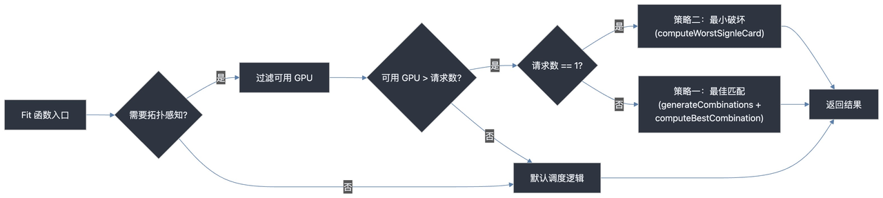
调度决策的核心逻辑位于设备端 pkg/device/nvidia/device.go 的 Fit() 函数中。当该函数通过 Annotation 识别到需要进行拓扑感知调度后,会基于节点上报的"设备分数表",根据请求的 GPU 数量,自动切换寻优策略。
// File: pkg/device/nvidia/device.go

func (nv *NvidiaGPUDevices) Fit(...) {
        // ...
        needTopology := util.GetGPUSchedulerPolicyByPod(device.GPUSchedulerPolicy, pod) == util.GPUSchedulerPolicyTopology.String()
        // ...
        // (过滤出所有满足基本条件的空闲 GPU: tmpDevs)
        // ...
        if needTopology {
                if len(tmpDevs[k.Type]) > int(originReq) {
                        if originReq == 1 {
                                // 单卡任务
                                lowestDevices := computeWorstSignleCard(nodeInfo, request, tmpDevs)
                                tmpDevs[k.Type] = lowestDevices
                        } else {
                                // 多卡任务
                                combinations := generateCombinations(request, tmpDevs)
                                combination := computeBestCombination(nodeInfo, combinations)
                                tmpDevs[k.Type] = combination
                        }
                        return true, tmpDevs, ""
                }
        }
        // ...
}
Fit 函数的整体决策逻辑可以用下图来概括:
策略一:多卡任务的"最佳匹配"原则
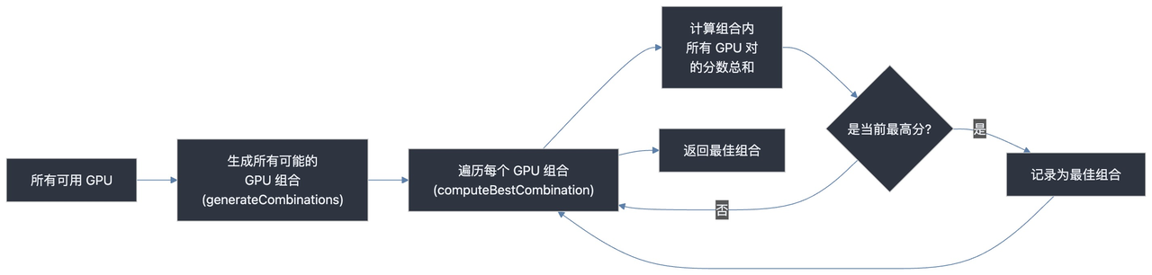
当 Pod 请求多于 1 个 GPU 时,算法的目标是寻找内部通信总分最高的 GPU 组合。
代码实现:Fit 函数首先会找出节点上所有满足基本资源需求的空闲 GPU。然后:
- 调用
generateCombinations函数,找出这些空闲 GPU 的所有可能组合。 - 调用
computeBestCombination函数,该函数会遍历所有这些组合,并利用"设备分数表",计算每个组合内部所有设备对的分数总和。 - 最终,
Fit函数会选择那个分数总和最高的组合作为分配结果。这确保了任务被分配到内部连接最紧密、通信效率最高的 GPU"集群"上。
其核心寻优逻辑如下:
策略二:单卡任务的"最小破坏"原则
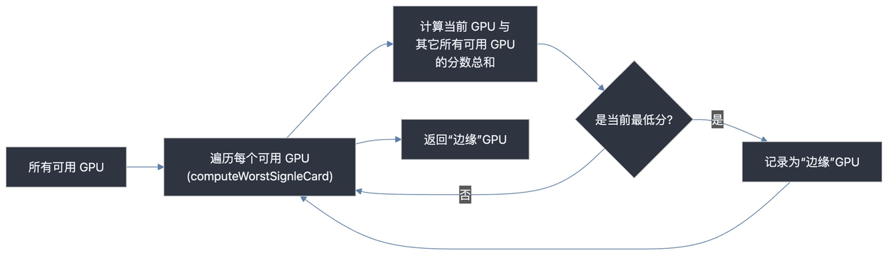
当 Pod 只请求 1 个 GPU 时,算法的目标转为选择一个与其他可用 GPU 连接最"疏远"的卡,以保护拓扑完整性。
代码实现:Fit 函数会调用 computeWorstSignleCard 函数。该函数会遍历所有可用的单个 GPU,并利用"设备分数表",计算每个 GPU 与其他所有可用 GPU 的分数总和。最终,它会选择那个总分最低的 GPU。这块卡通常位于拓扑的"边缘"位置,分配它对整体拓扑网络的破坏最小。
其核心寻优逻辑如下:
四、使用方式
用户只需一个 Annotation 即可启用拓扑感知调度。调度器会根据任务请求的 GPU 数量,自动应用"最佳匹配"或"最小破坏"策略。
apiVersion: v1
kind: Pod
metadata:
  name: gpu-topology-aware-job
  annotations:
    # 启用"拓扑感知"调度策略。
    hami.io/gpu-scheduler-policy: "topology-aware"
    # 调度器将自动基于设备间的通信分数,
    # 为多卡任务选择内部连接最紧密的组合,
    # 或为单卡任务选择对拓扑破坏最小的设备。
spec:
  containers:
  - name: cuda-container
    image: nvidia/cuda:11.6.2-base-ubuntu20.04
    command: ["sleep", "infinity"]
    resources:
      limits:
        # 请求 4 个 GPU
        nvidia.com/gpu: "4"
五、总结
HAMi 对 NVIDIA GPU 的拓扑感知调度,在设计上体现了清晰的工程哲学:用动态发现代替静态配置,用远见决策代替短视分配。其设备端的双策略寻优算法,通过消费预先计算好的"通信分数",兼顾了当前任务的极致性能与集群资源的长期健康,构成了一套成熟、高效的 GPU 调度方案,为用户在云原生环境中运行大规模 AI 训练与 HPC 任务提供了坚实的性能保障。
参考资料
- 设计文档:NVIDIA GPU Topology Scheduler
- 使用文档:NVIDIA GPU 拓扑调度启用指南
- 相关 PRs:
再次由衷感谢社区开发者 @lengrongfu,@fyp711 对该特性的贡献!